How to open ASUS ROG Zephyrus G14 GA402 (2023) – disassembly and upgrade options

Opening the Laptop
- Undo the 11 Phillips-head screws securing the bottom panel of the laptop. Note that the three middle screws are covered by rubber caps. Remove these caps with a flathead screwdriver first.
- Start prying the bottom panel from the bottom right corner, where the captive screw is located, using a plastic pry tool.
Caution: Be gentle to avoid damaging the internal components or the clips that hold the bottom panel in place.

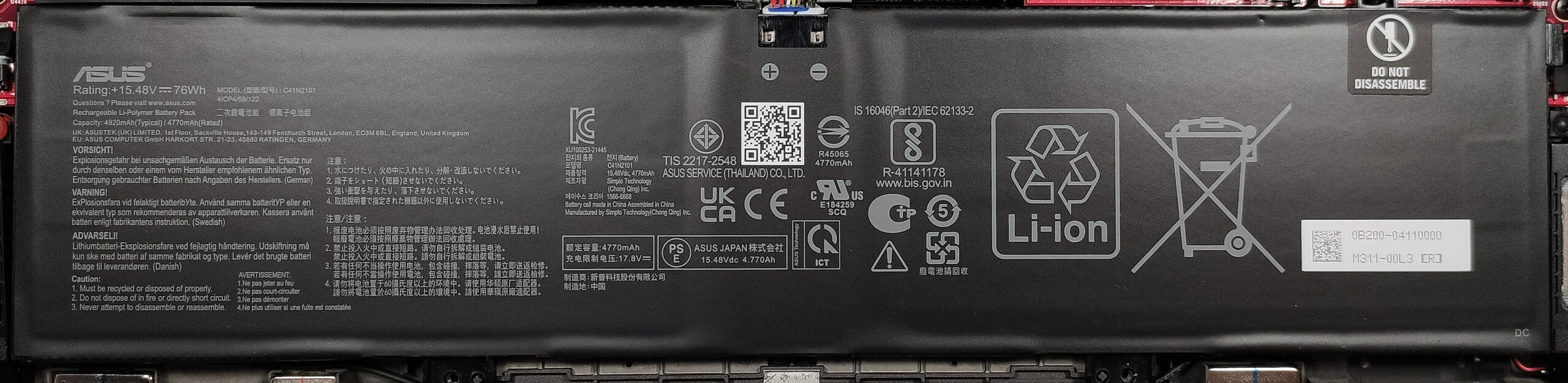
Removing the Battery
- Disconnect the battery connector from the mainboard by gently pulling it out with a plastic tool.
- Note that one of the screws securing the battery is located beneath the SSD. Remove the SSD first to access this screw.
- Undo the two Phillips-head screws and lift the battery out of its compartment.
More info: The laptop is equipped with a 76Wh battery, capable of 20 hours of web browsing or 10 hours of video playback, which is excellent for a gaming laptop.
Upgrading the RAM
- Locate the single SODIMM slot available for RAM upgrades.
- If adding new RAM, ensure it is DDR5-4800MHz to match the soldered memory’s speed and support dual-channel mode.
More info: The laptop supports up to 32GB of DDR5-4800MHz memory in dual-channel mode. The soldered memory also operates in dual-channel when the RAM slot is filled.

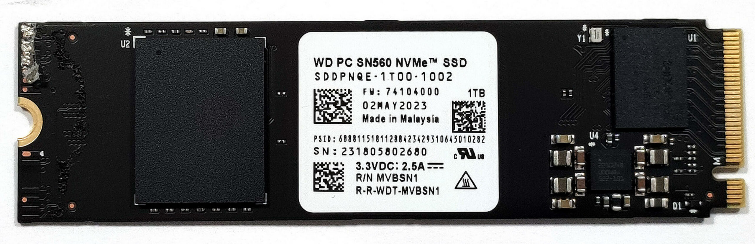
Upgrading the SSD
- Identify the single M.2 slot for a 2280 Gen 4 SSD.
- Remove the SSD by undoing its securing screw, then gently pull out the NVMe SSD.
- Insert the new SSD and secure it with the screw. Ensure the cooling pad is properly aligned for optimal heat dissipation.
More info: The laptop has one M.2 slot for storage expansion, supporting 2280 Gen 4 SSDs.

Dismantling the Vapor Chamber Cooling System
- Remove the protective stickers from the left and right heat sinks to expose the screws.
- Disconnect the connectors on the left side and slightly lift the other one as well.
- Undo the 8 captive Phillips-head screws fixing the cooling system to the base.
- Remove the two Phillips-head screws above the two heat pipes.
- Undo the two pairs of screws securing the fans and lift them out of the chassis.
- Carefully raise the lower part of the cooling system and lift it away from the motherboard.
More info: The vapor chamber system includes a large central cooling area, dedicated heat pipes for each chip, and four large heat sinks. It uses liquid metal on the CPU die and thermal paste on the GPU chip, with soft thermal interface material (“Thermal Putty”) applied to other components.
Caution: Handle the liquid metal and thermal paste with care to avoid spillage and ensure optimal thermal contact.


![[June 2026] Best-Selling Laptop Brands on Amazon Global – Apple’s Unrivaled Dominance in Units and Revenue](https://laptopmedia.com/wp-content/uploads/2026/07/GLOBAL-Best-Brands-400x225.jpg)
![[June 2026] Amazon Global: Top 10 Best-Selling Laptops – Apple’s New MacBook Neo Storms to #1, Reshaping the Market with Affordability](https://laptopmedia.com/wp-content/uploads/2026/07/Best-Selling-Laptops-GLOBAL-Top-10-400x225.jpg)
![[June 2026] Amazon Global: Top 10 Best-Selling Gaming Laptops – Acer’s Nitro V 16S AI Dominates Sales, While ASUS Leads Overall Revenue](https://laptopmedia.com/wp-content/uploads/2026/07/Best-Selling-Gaming-Laptops-GLOBAL-Top-10-400x225.jpg)
![[June 2026] Global Ranking of Best-Selling Laptop GPUs on Amazon – NVIDIA RTX 5060 is the Top-Selling Dedicated GPU](https://laptopmedia.com/wp-content/uploads/2026/07/Best-Selling-GPUs-GLOBAL-Top-10-400x225.jpg)
![[June 2026] Global Ranking of Best-Selling Laptop CPUs on Amazon – Apple M5 Dominates, AMD Ryzen 7 260 Gets Solid Premium Share](https://laptopmedia.com/wp-content/uploads/2026/07/Best-Selling-CPUs-GLOBAL-Top-10-400x225.jpg)